Dreamcast AICA MIDI output
My alternate ScummVM backend for Dreamcast has drivers for two different hardware methods of transmitting MIDI audio data. The idea of controlling classic synthesizers with a Dreamcast is what got me started hacking on ScummVM in the first place.
One of the MIDI drivers is for the official Dreamcast MIDI Interface Cable which plugs into the Dreamcast serial port. Unfortunately, these cables are quite rare and are expensive when they can be found.
The other MIDI driver is for the AICA sound processor’s MIDI output. While I waited months for a MIDI Interface Cable to show up for sale on eBay I looked into using AICA’s MIDI output instead, and it turned out to be easy to install a MIDI connector for it. Using the AICA MIDI output instead of the MIDI Interface Cable also frees up the serial port for other uses, like an SD card or a debugging cable.
While some exotic Dreamcast hardware, like dev units and the Divers 2000, have actual MIDI connectors for the AICA signals, standard Dreamcasts only expose them on the G2 bus, on pins 49 (AICA MIDI out) and 50 (AICA MIDI in). You can wire MIDI connectors directly to these pins on the motherboard G2 connector, but I found value in adding the MIDI connector to a Dreamcast modem instead. That way you keep your Dreamcast pristine, and you can swap the MIDI modem between consoles. That’s the modification I describe below. It’s pretty easy to accomplish and requires only common tools and basic soldering skills.
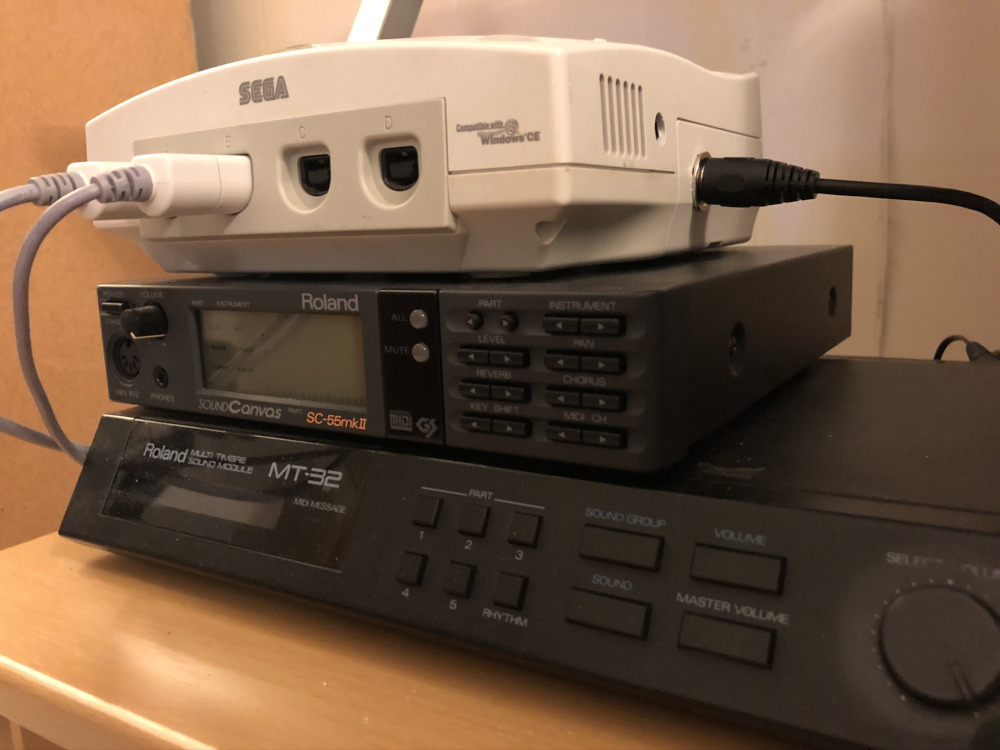
A MIDI-enabled Dreamcast stacks nicely on a Roland SC-55 and MT-32:
Software support
ScummVM
My alternate ScummVM backend for Dreamcast will output MIDI data through the AICA if you select “Dreamcast AICA” as the MIDI driver from the launcher. It also has a “Dreamcast MIDI Interface Cable” driver for the official cable.
KallistiOS
This patch adds a snd_midi() function to the KallistiOS sound API.
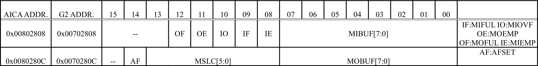
Registers
The AICA can write MIDI bytes to the lower 8 bits of 0x0080280C. The 12th bit of 0x00802808 indicates that the output buffer is full. The 11th bit of 0x00802808 indicates that the output buffer is empty.
Requirements
Materials
- A Dreamcast modem. I don’t think the revision should matter as we are only using it for the G2 connector.
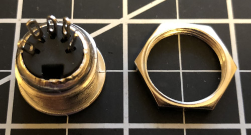
- A female MIDI connector. I used this one.
- Two 220 Ω resistors
- ~30 AWG wire
- Heat shrink tubing or electrical tape
Tools
- A Phillips screwdriver
- A soldering iron
- A drill for drilling a hole in the modem case
- A file and/or a rotary tool for detail work on the hole (optional)
Skills
- Basic soldering
Step-by-step instructions
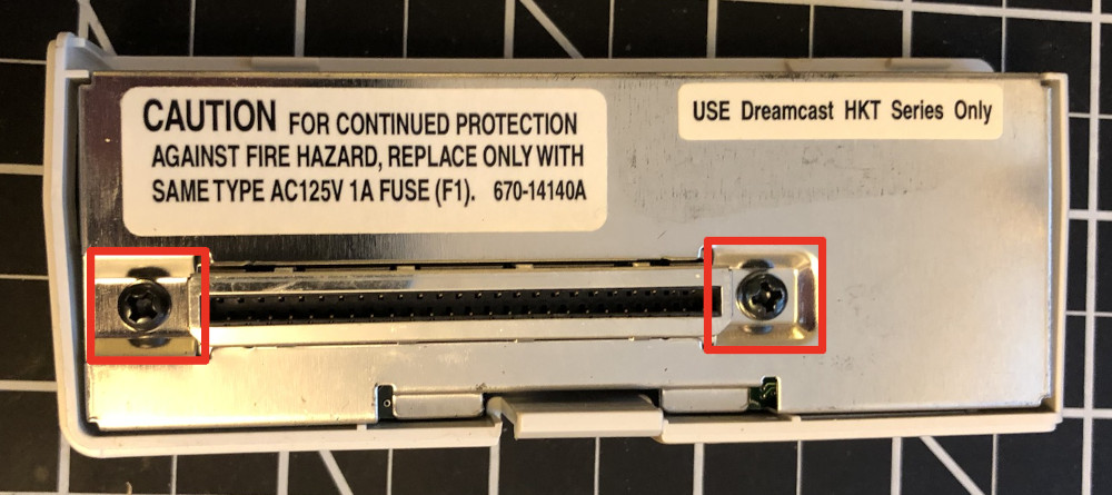
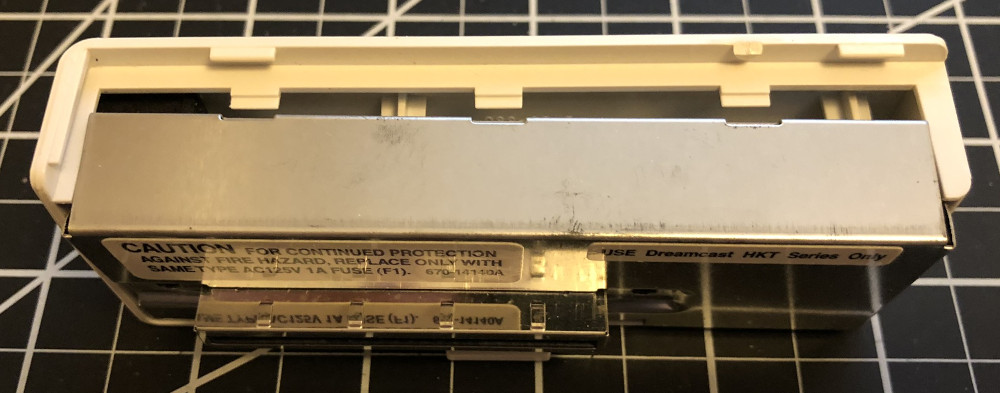
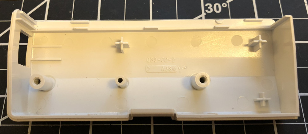
1. Disassemble the modem
Unscrew the screws highlighted in red.
Remove the metal shields and circuit board from the plastic case. This can be a bit tricky, but keep wiggling them, and they will come out.

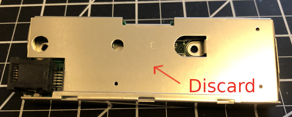
Remove the two metal shields from the circuit board. Discard the inside shield (marked in red below). It will get in the way of the MIDI connector, so the modem will be reassembled without it at the end.
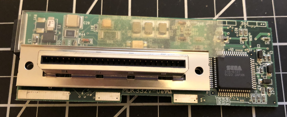
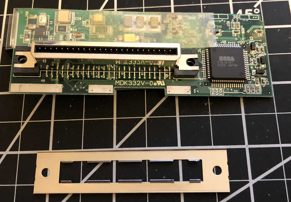
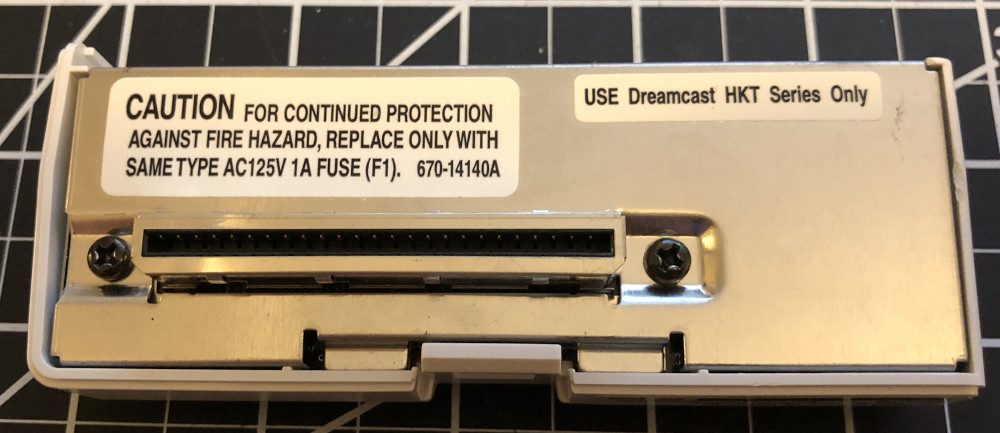
Finally, remove the small metal shield from around the G2 connector. It is attached tightly, so you will need to wiggle it back and forth as you lift it off.
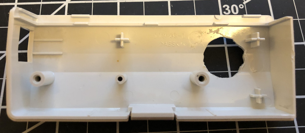
2. Make a hole in the plastic case
Now make a hole in the plastic case for the MIDI connector.
The hole needs to meet a few constraints.
It needs to be large enough that you can insert the MIDI connector from the outside, and it needs enough clearance around the edge so that you can attach and completely turn the nut that secures the MIDI connector to the inside of the case.
It also needs to be in a location that can accommodate the depth of the MIDI connector so that it isn’t blocked by the G2 connector or anything else on the PCB when the case is reassembled. (You can bend the pins on the connector to get a little more room.)
You can use a drill to make an initial hole and then apply lateral force with the drill to enlarge the hole. You will probably have cleaner results using a rotary tool and/or a file as you get closer to the edges. Mine did not come out entirely circular, but the MIDI connector has a bevel that covers it up from the outside, so it isn’t too noticeable.
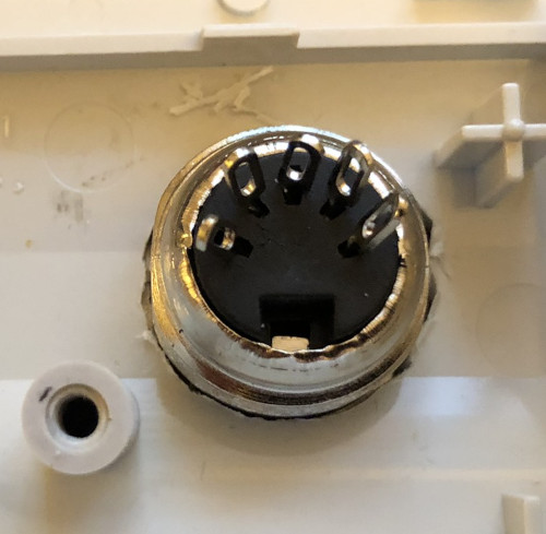
3. Prepare the connector
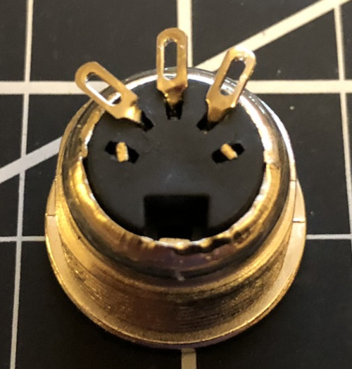
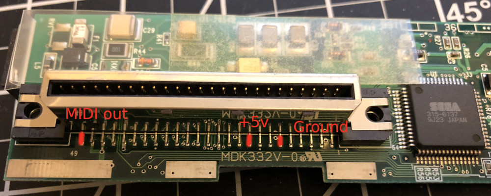
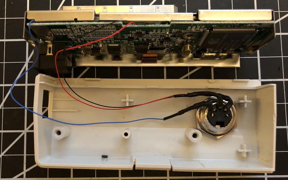
Only three of the MIDI connector’s pins are used for MIDI. The two outer ones are not connected. The connections you need to make to three inner pins are, in left-to-right order from the back of the connector, MIDI out, ground, and +5V.
In these pictures I used three different colors of wire: red for +5V, black for ground, and blue for MIDI out.
You can start by clipping off the two outer pins with wire cutters and bending the three inner pins to the side. Bending the pins helps the connector fit in the modem case.
Shorten the leads on each of the 220 Ω resistors and solder one to the left-most pin (MIDI out) and one to the right-most pin (+5V). The middle pin (ground) does not need a resistor.
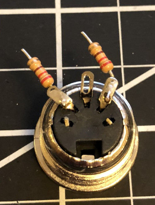
Solder 6 inch (15 cm) lengths of wire to the other end of each resistor and to the ground pin. 6 inches is more wire than you need, but you can coil the extra wire into the modem case when you put it back together.

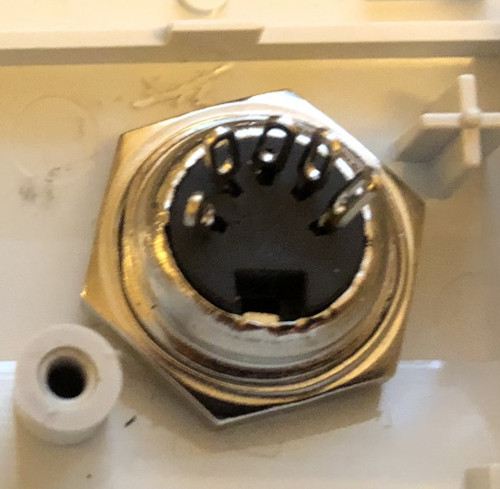
4. Install the connector
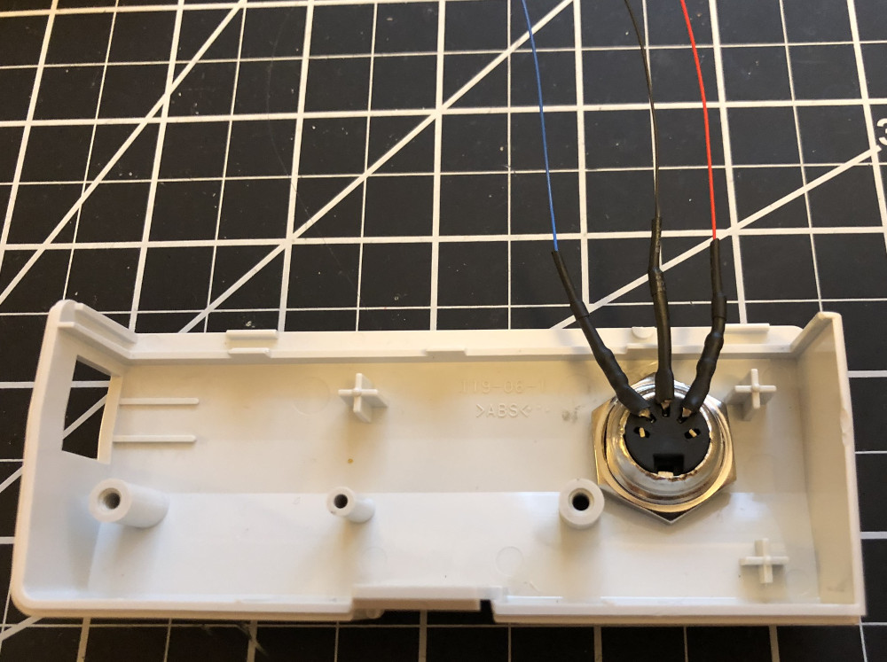
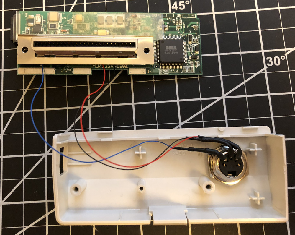
Run the wires through the hole in the modem case, put the connector through the hole, and tighten the nut around it.
Then insulate the exposed metal of the pins and resistors so that they can’t come in contact with each other or with the metal casing of the connector. I used heat shrink tubing here, but electrical tape will also work.
5. Solder to the G2 connector pins
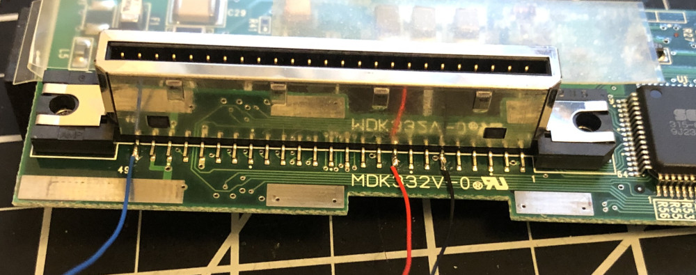
Solder the wires to these three pins on the modem circuit board’s G2 connector:
- Pin 11: Ground
- Pin 17: +5V
- Pin 49: MIDI out
6. Reassemble the modem
Slide the connector shield back on to the G2 connector.
Put the circuit board in the plastic case without the outer metal shield to test fit and to make sure that no metal part of the MIDI connector, resistors, or wires can touch anything on the circuit board. If you are not using heat shrink tubing, you should cover with electrical tape the part of the circuit board that is near the MIDI connector.
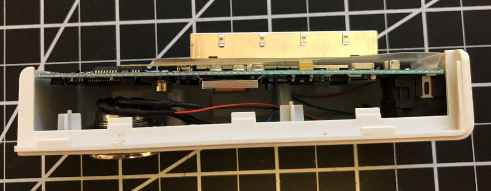
Attach the outer metal shield to the circuit board. It should only fit loosely. Make sure the MIDI out wire isn’t pinched between the shield and the circuit board.
Put the circuit board with metal shield into the plastic case and screw in the two screws you removed in step 1.
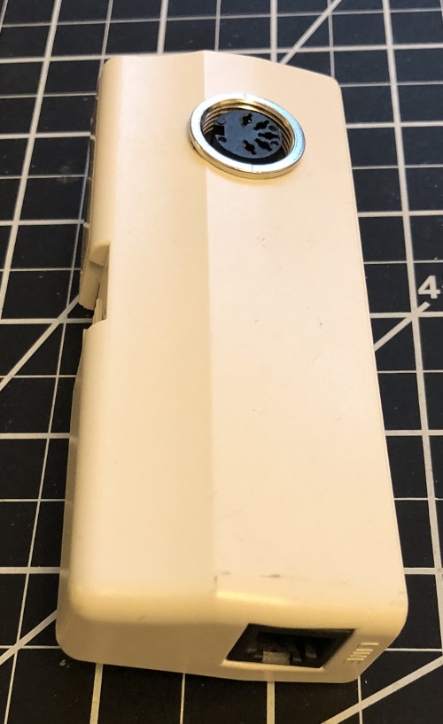
That’s it! Here’s the finished product: