Pioneer SX-950 HDMI CEC Volume Control
When my ’90s-era stereo receiver stopped working in 2017 I was lucky enough to find on craigslist an old Pioneer model from the ’70s, a Pioneer SX-950.
My dad had a similar model when I was growing up, and it has a lot of nostalgia value for me. It has a beautiful front panel, but you really have to experience it to appreciate it - the switches, buttons, and knobs all have a great tactile response. I especially like how the big tuning knob is weighted so that it has some momentum when you spin it (which comes in handy because it takes a long time to get from one end of the radio spectrum to the other), and the warm glow of the indicator lights and panel lighting evokes a cozy fireplace.
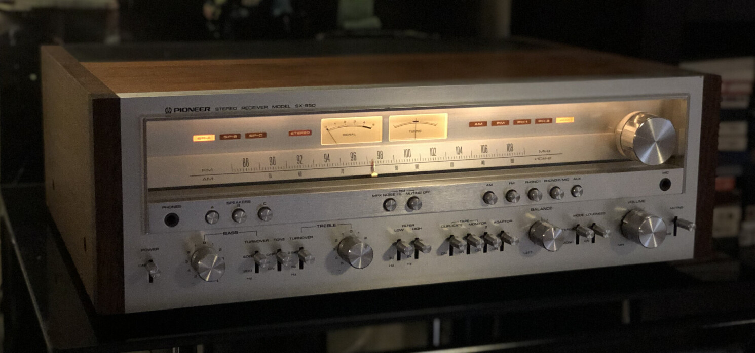
It sounds all right too.
The only problem is that it doesn’t have a remote control, which I don’t mind when I’m just listening to music, but when I’m watching a TV show or a movie, physically standing up using my own legs and walking over to the receiver to manually turn the volume knob is a terrible chore. It’s hard to imagine how our ancestors survived before remotes became commonplace.
So I started working on a plan to replace the volume potentiometer with a motorized potentiometer and build a device to remotely operate the potentiometer motor. I had this kicking around in my head for about three years, doing some research here and there, before I finally dove into it this spring.
Research
Finding a suitable potentiometer
The ideal potentiometer for this project would have the following characteristics:
- 50K resistance like the original potentiometer.
- It needs a 25mm shaft to stick out from the panel far enough for the volume knob to attach to it.
- Potentiometer shafts come in different shapes, but this volume knob is designed for a knurled shaft.
- It needs at least 2 gangs, one each for the left and right audio channels.
- Because human volume perception is not linear, the resistance should have a logarithmic taper.
- To support the receiver’s loudness compensation feature, it needs a center tap.
Unfortunately, no such part exists, so I had to start compromising.
The center tap requirement was the first to go. It didn’t take long for me to realize that I was not going to find a center-tapped motorized pot, and while some brave souls have done after-market center taps, I simply convinced myself that loudness compensation is a gimmick that I don’t need. Everything else should work fine with the loudness switch disconnected.
Still, after scouring parts suppliers and eBay and contacting manufacturers directly, the best I could do was 4/5 of the remaining constraints. I tried to get creative and swap different-sized shafts between parts, and tried filing down a D shaft to fit the receiver’s knurled volume knob. I was not successful at either.
Finally I learned from reading an audio forum that the resistance of the pot may not need to exactly match the original 50K. The volume depends on the ratio of the resistance of the potentiometer setting which is independent of the resistance rating of the part. The resistance rating does need to match the impedance of the input, or something, but that’s beyond my limited understanding of analog electronics. I decided it was worth trying, and found a 10K pot that met the other 5 constraints: a Bourns PRM162-K425K-103A2.
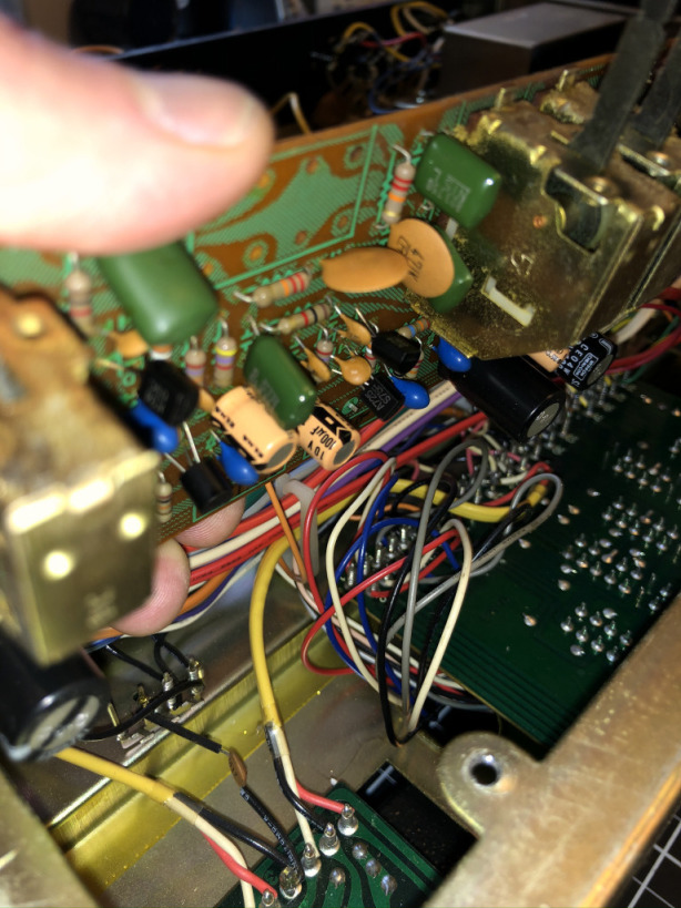
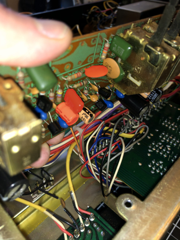
Having settled on and purchased a potentiometer, I opened up the receiver to figure out how all of this was going to fit together… and it wasn’t. The motorized pot is quite a bit larger than the original (mostly because of the big motor sticking out the back), and there were a few capacitors soldered to the board where the motor needs to go.
You can see the size difference in the photo on the left - the motorized pot is in the foreground. Something would have to be done with the highlighted capacitors on the right.
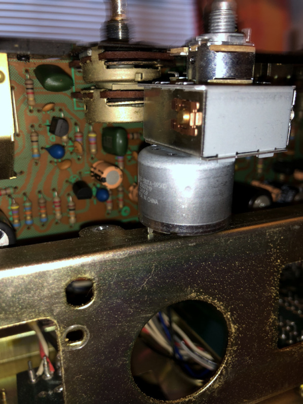
Fortunately, there’s all this “wasted” space on the bottom on that board. There’s about half inch of clearance between the board and the receiver’s bottom panel, plenty of room to relocate the problematic capacitors to the other side of the board if they are laid on their sides.
Another issue is the new potentiometer’s footprint doesn’t match the original, but I figured I could connect it to the board using wires. The shaft is bolted onto the front panel, so the pot doesn’t need to align perfectly with the old one and can hang loose from the board.
Remote control
For remotely operating the potentiometer motor, I thought of a few options:
-
A custom IR or RF solution, maybe mimicking an existing product’s protocol so that I could program my TV’s remote to control it.
-
I believe volume control signals can be sent over an optical cable, but I couldn’t find any documentation on it, so I think whatever exists there is all proprietary.
-
HDMI CEC (Consumer Electronics Control) - my TV has an HDMI ARC (Audio Return Channel) port for sending audio over HDMI to a receiver, and it also transmits CEC volume control commands to connected audio devices.
I went with HDMI CEC because it’s actually documented in the HDMI spec and looked pretty straightforward to implement.
Installing the motorized potentiometer
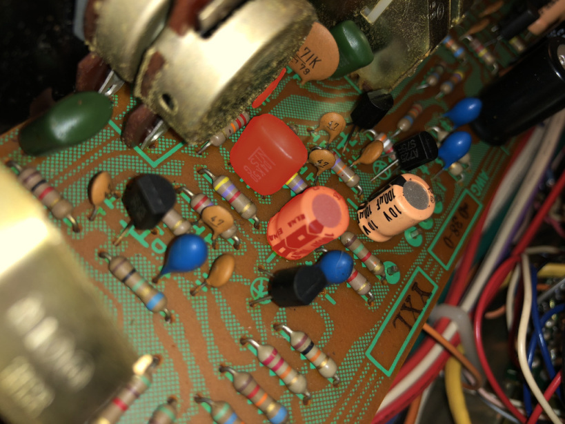
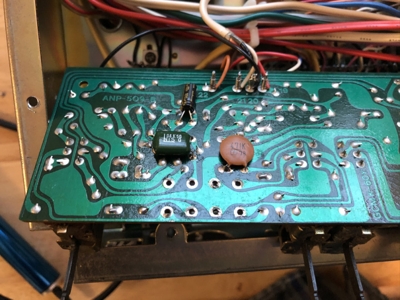
Here’s the receiver’s Flat Amplifier Assembly after I removed the old pot. The highlighted capacitors needed to be removed and soldered onto the other side of the board to make room for the motorized potentiometer.
I removed them and soldered them to the same points on the bottom of the board…
…and wired up the new potentiometer…
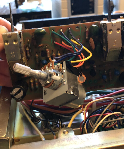
There was a small problem with the panel that the potentiometer mounts to. You can see there’s a “key” to the right, and because it does not quite match the original, the shaft is offset to the right by about a millimeter. This small offset was actually really noticeable when I put the front panel back on, so I went back and filed down the keyhole on the panel so that I could center the shaft.
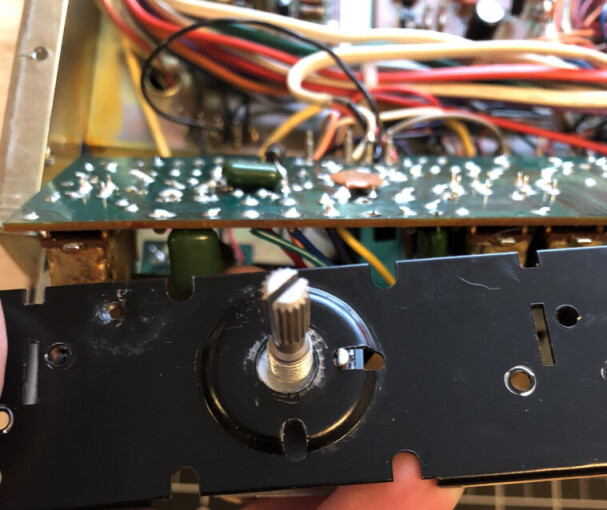
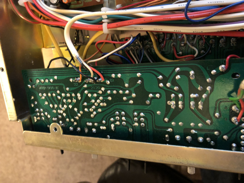
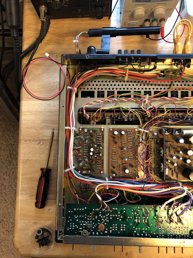
Here’s the whole assembly with the new pot installed. I planned to have the device that controls the motor live outside of the receiver, so I attached the pot’s motor to a connector long enough to hang outside the chassis.
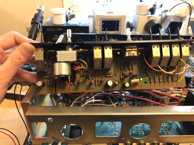
Here’s the bottom of the inside of the receiver. You can see the displaced capacitors at the bottom of the photo and the new motor wires running from the Flat Amplifier Assembly to the connector on the top left.
The receiver sounded great with the new pot!
Hardware
Next I just needed a device to listen for CEC volume control signals and operate the volume pot motor accordingly.
HDMI CEC motor control
For this part I just needed a microcontroller to talk HDMI CEC with the TV, a motor driver to control to the motorized pot, and a way to power the two. I used an ATTINY4313 and an L293DNE half-H driver and powered it all over USB. The CEC bus is open-collector and pulled up by the TV, so the CEC signal can be connected directly to a tristate pin on the microcontroller. I clocked the microcontroller with an external crystal because I found that the CEC wire protocol timing is sensitive enough that it could be affected by the variance of the AVR’s internal clock.
 EDIT: The MISO and SCK pins were swapped in the original
schematic but are
fixed now.
EDIT: The MISO and SCK pins were swapped in the original
schematic but are
fixed now.
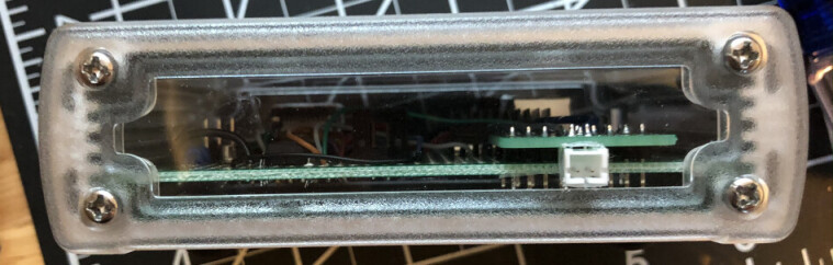
This was a simple enough design that I was able to throw it all together on a prototype board. About half of the wiring here is for the in-system programming and UART (for debugging) headers.
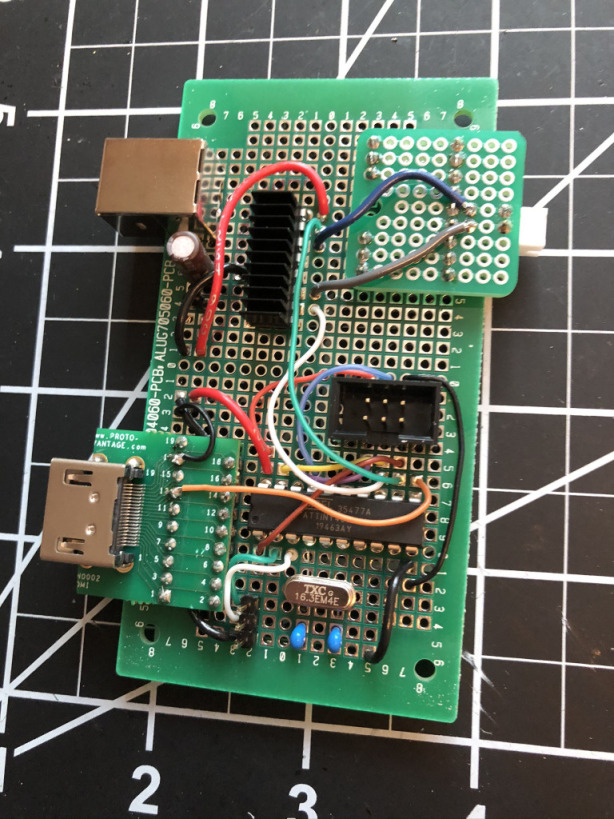
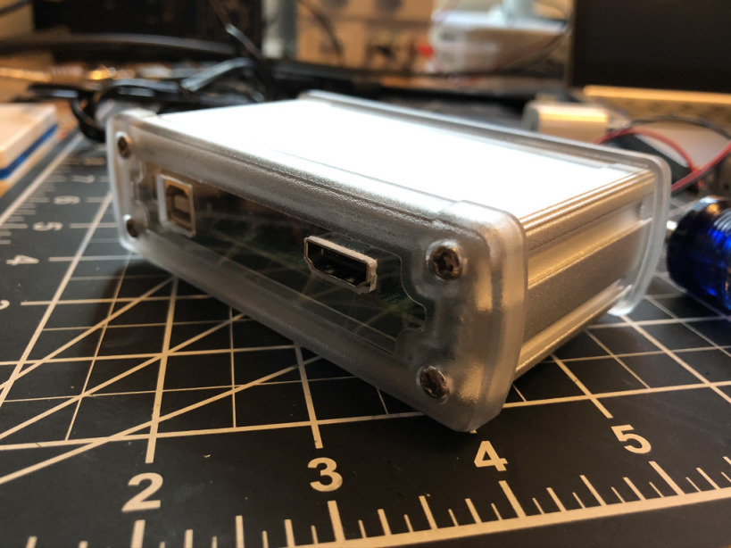
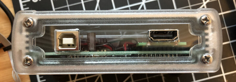
I put it in a nice extruded aluminum case that sort of but doesn’t really match the finish on the receiver and cut some crude connector holes in the enclosure’s plastic side panels. The board has a USB connector for power, an HDMI connector to connect it to the TV, and a two-pin connector to connect to the motorized potentiometer in the receiver.
Software
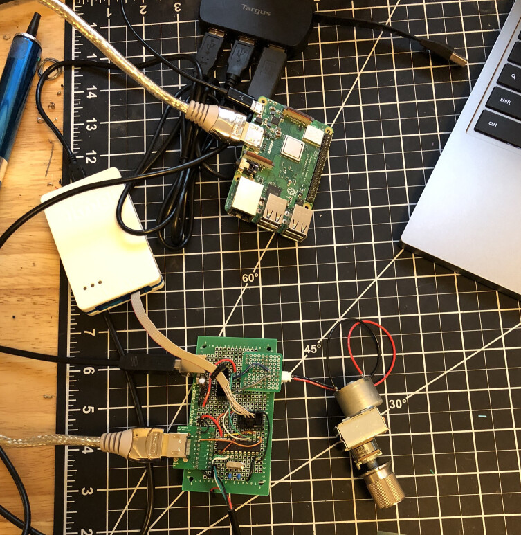
Finally the fun part! For the initial development I tested using a separate motor and libcec’s cec-client on a Raspberry Pi to generate test HDMI CEC commands. From what I could tell, software support for HDMI CEC is pretty spotty, but the Raspberry Pi is one of the few well-supported devices.
My TV is a little more particular about handshaking before it decides a device is worthy of CEC volume control commands, so I had to implement responses to some additional HDMI messages to get it work with the TV. My code works well with my LG WebOS-based TV, but I wouldn’t be surprised if it doesn’t work out-of-the-box with other makes or models.
I included some fail-safes because a mistake could burn out the potentiometer motor or blow a speaker. The motor is never engaged without first setting up a timer interrupt to stop the motor, so even if the microcontroller gets lost somewhere in the CEC code, the motor should never run continuously. The AVR watchdog timer will also stop the motor if it really hits the fan. I power the device from one of the receiver’s switched power outlets, so it’s only powered on when it’s in use.
The code is here: https://github.com/tsowell/avr-hdmi-cec-volume/blob/master/main.c
It might be useful to someone implementing the CEC protocol on an AVR.
Results
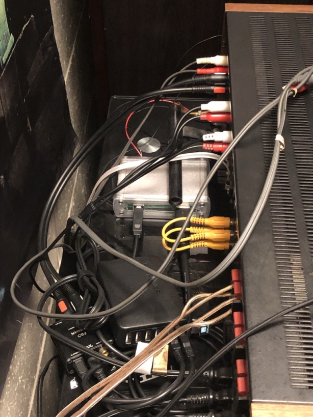
Here’s the device hooked up to everything behind the receiver and an animated GIF of the volume knob turning under control of the TV remote.
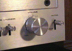
It can do both fine and coarse adjustments.
For fine adjustments, momentary volume button presses on the TV remote cause the knob to turn for a duration that corresponds to a small but audible change in volume. The receiver’s volume control is pretty sensitive, so each momentary press produces a very small rotation.
For coarse adjustments, when a volume button on the TV remote is held down, the knob turns continuously until the remote button is released.
The knob can also still be turned by hand.
To my surprise, it has worked flawlessly for the five months it has been in use, but every now and then I still catch myself getting up out of my seat to change the volume…